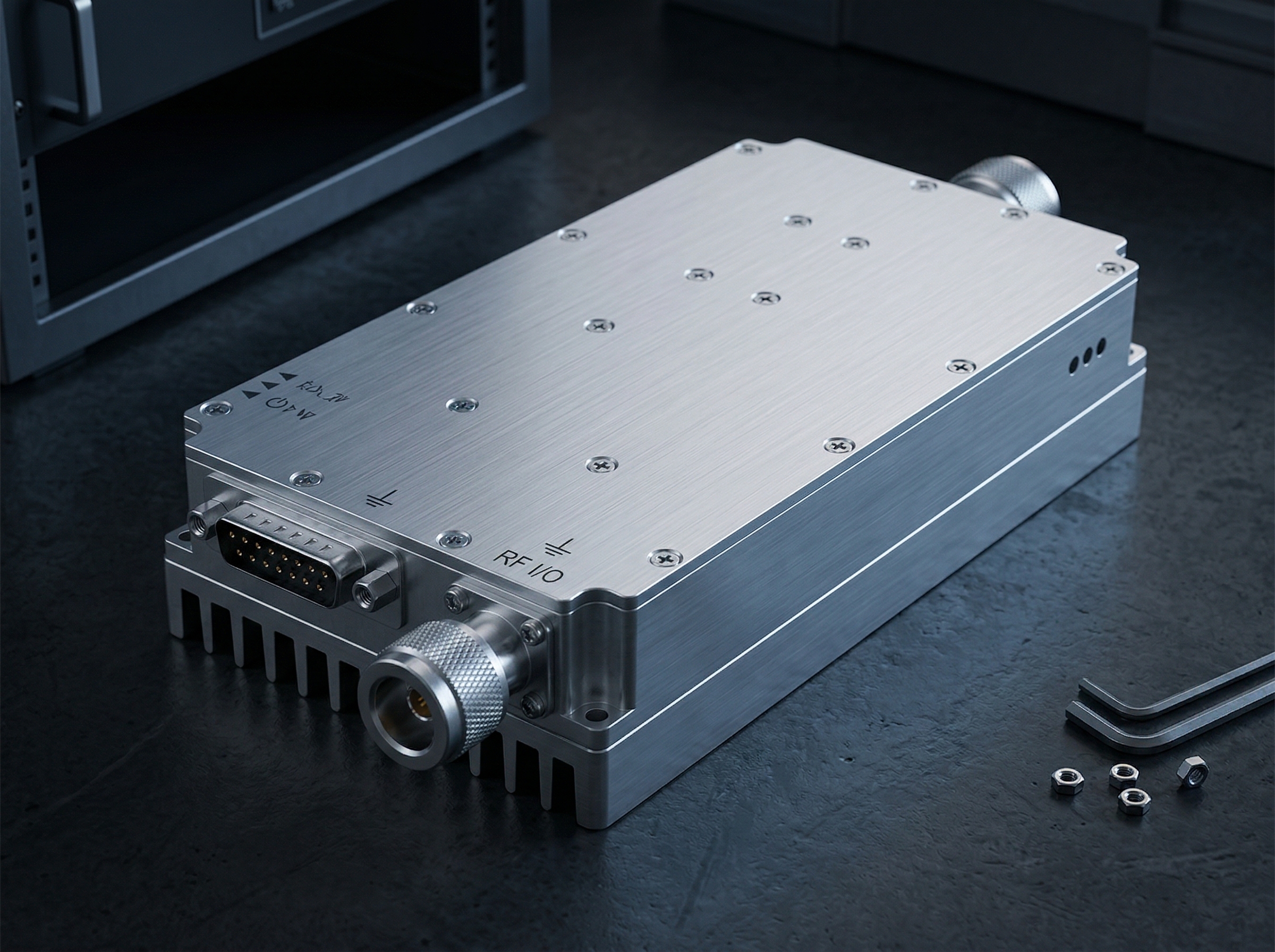
CorelixRF | RF Systems Solutions
300–2700 MHz RF Power Amplifier Manufacturer | 30W–200W GaN Modules | CorelixRF
Factory-Direct RF Manufacturing

300–2700 MHz
RF Power Amplifier
Manufacturer

Factory-direct GaN RF power amplifiers from 30W to 200W for CW and pulse applications. Built for broadband transmission, SDR front-end integration, and OEM/ODM RF platform development. Engineered and manufactured in-house.
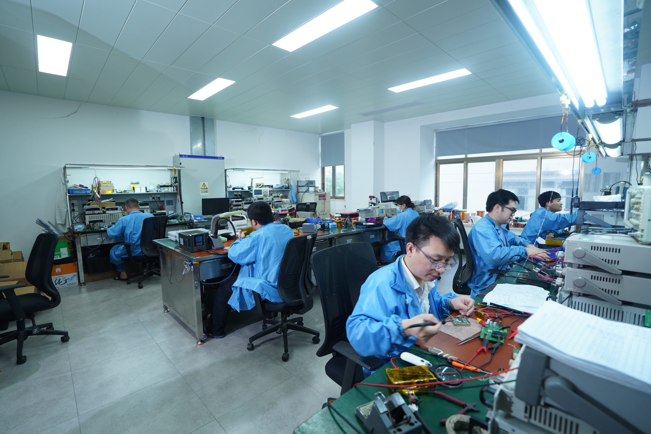
CorelixRF 300–2700 MHz GaN RF power amplifier module — top view showing RF connectors, heatsink baseplate, and housing structure
Model Group: CRF-PA-300M2700M
FREQUENCY RANGE300 – 2700 MHz
OUTPUT POWER30 W – 200 W
SUPPLY VOLTAGE28 V DC
PROCESSGaN-on-SiC
IMPEDANCE50 Ω
GaN-on-SiC
Process Technology
50 Ω
System Matching
VSWR Prot.
Reflected-Power Protection
OEM / ODM
Factory Manufacturing
Manufacturer Advantage

Why Source Directly
From CorelixRF

CorelixRF manufactures broadband RF power amplifiers for customers who need more than a catalog part. We support project evaluation from frequency planning and drive-level review to thermal design confirmation and final production delivery.

01
RF
In-House RF Engineering
Frequency planning, gain-stage review, drive-level confirmation, and thermal-path assessment before sample build. You work directly with our RF engineers, not a sales intermediary.
02
Factory-Level Customization
Connector types, housing dimensions, supply architecture, sub-band optimization, and labeling can be adjusted for OEM/ODM projects. Customization begins with an application review, not a purchase order.
03
Broadband Test Validation
Representative units are verified for gain response, output power behavior, and reflected-power protection before release. Sample test data available during engineering review for selected models.
04
Batch Production Support
From prototype builds to repeat production, model configuration and test status remain traceable. We maintain configuration history to ensure consistency across production runs.
CorelixRF RF engineering lab — engineer operating VNA test bench with power amplifier module under measurement
Product Guide

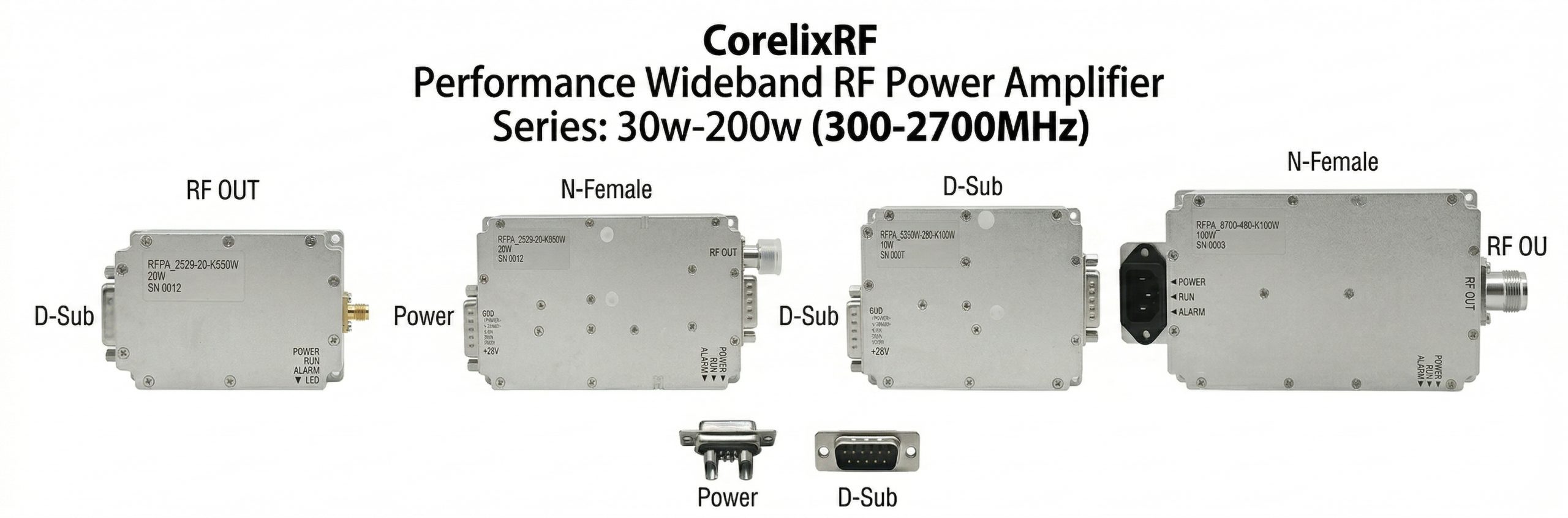
Standard 300–2700 MHz RF Power Amplifier Configurations

Compare models by output power, gain, operating mode, and supply voltage. Click a model number for full specifications. For projects requiring specific gain flatness or custom thermal management, contact our engineering team for a recommended configuration.

CorelixRF CRF-PA-300M2700M series — 30W, 50W, 100W, 150W, and 200W broadband RF power amplifier modules
Model Number Frequency Range CW / Pulse Output Power Typical Gain Supply Voltage Cooling Datasheet Inquiry
CRF-PA-300M2700M-30W 300–2700 MHz CW / Saturated 30 W ~45 dB 28 V DC Air 📄 PDF Request 30W Review →
CRF-PA-300M2700M-50W 300–2700 MHz CW / Saturated 50 W ~47 dB 28 V DC Air 📄 PDF Request 50W Review →
CRF-PA-300M2700M-100W 300–2700 MHz CW / Saturated 100 W ~50 dB 28 V DC Air 📄 PDF Request 100W Review →
CRF-PA-300M2700M-150W 300–2700 MHz CW / Saturated 150 W ~52 dB 28 V DC Air 📄 PDF Request 150W Review →
CRF-PA-300M2700M-200W 300–2700 MHz CW / Saturated 200 W ~53 dB 28 V DC Air 📄 PDF Request 200W Review →
Use Cases

Typical Applications

The 300–2700 MHz frequency range and 30W–200W power range make this series suitable for broadband RF system integration across a wide variety of platforms.

RF power amplifier application environments — SDR integration, laboratory test bench, and vehicle-mounted tactical communication platform

SDR Front-End Power Stage

Suitable for broadband transmit chains where drive level, gain consistency, and thermal stability must be planned together. The wide frequency coverage allows a single module to cover multiple bands in a software-defined system.

Broadband RF Transmission Systems

Designed for wideband transmission architectures requiring reliable output power across the full 300–2700 MHz band without narrow-band tuning. Compatible with coaxial output interfaces commonly used in ground-based transmission systems.

Electronic Warfare Test Platforms

Supports pulse mode operation with configurable duty cycle and output power. Suitable for lab evaluation and test bench configurations where high reflected energy tolerance and VSWR protection are required. Also compatible with 2–6 GHz RF power amplifier modules for extended frequency coverage.

RF Laboratory Evaluation

Representative units are validated before shipment, making them suitable for evaluation in RF measurement environments. Test data can be provided to support lab integration and performance baseline comparisons.

OEM RF Integration Projects

For OEM projects requiring specific connector types, housing dimensions, or sub-band optimization, our custom RF power amplifier design capability allows adaptation based on target platform requirements. NDA-protected project review is available.

Tactical Communication Platforms

The combination of GaN-on-SiC efficiency, VSWR protection, and conduction-cooled packaging options makes this series compatible with mobile and vehicle-mounted communication platforms requiring compact thermal management.

Selection Guide

How to Select the Right
300–2700 MHz Amplifier

These are the factors to confirm before submitting an inquiry. Providing this information allows our team to give a focused engineering recommendation rather than a generic catalog suggestion.

01
Gain Flatness
Choose wideband (WB) configurations when broad frequency coverage matters more than peak efficiency. For narrowband applications, sub-band tuning can improve gain stability and power-added efficiency (PAE) within a target window.
02
Drive Level
Confirm your source output level early to determine whether a driver stage is required. Standard inputs are matched for −10 to 0 dBm. SDR sources with lower output should be reviewed before model selection.
03
Thermal Design
Cooling method should be selected according to duty cycle, ambient temperature, and installation structure. High-power-density designs generally require conduction or liquid cooling. Heatsink sizing must account for worst-case ambient conditions.
04
CW vs Pulse Operation
Pulse width, duty cycle, and required headroom should be reviewed before model selection. These parameters directly affect thermal budget and must be aligned with the cooling architecture during integration planning.
Test & Measurement

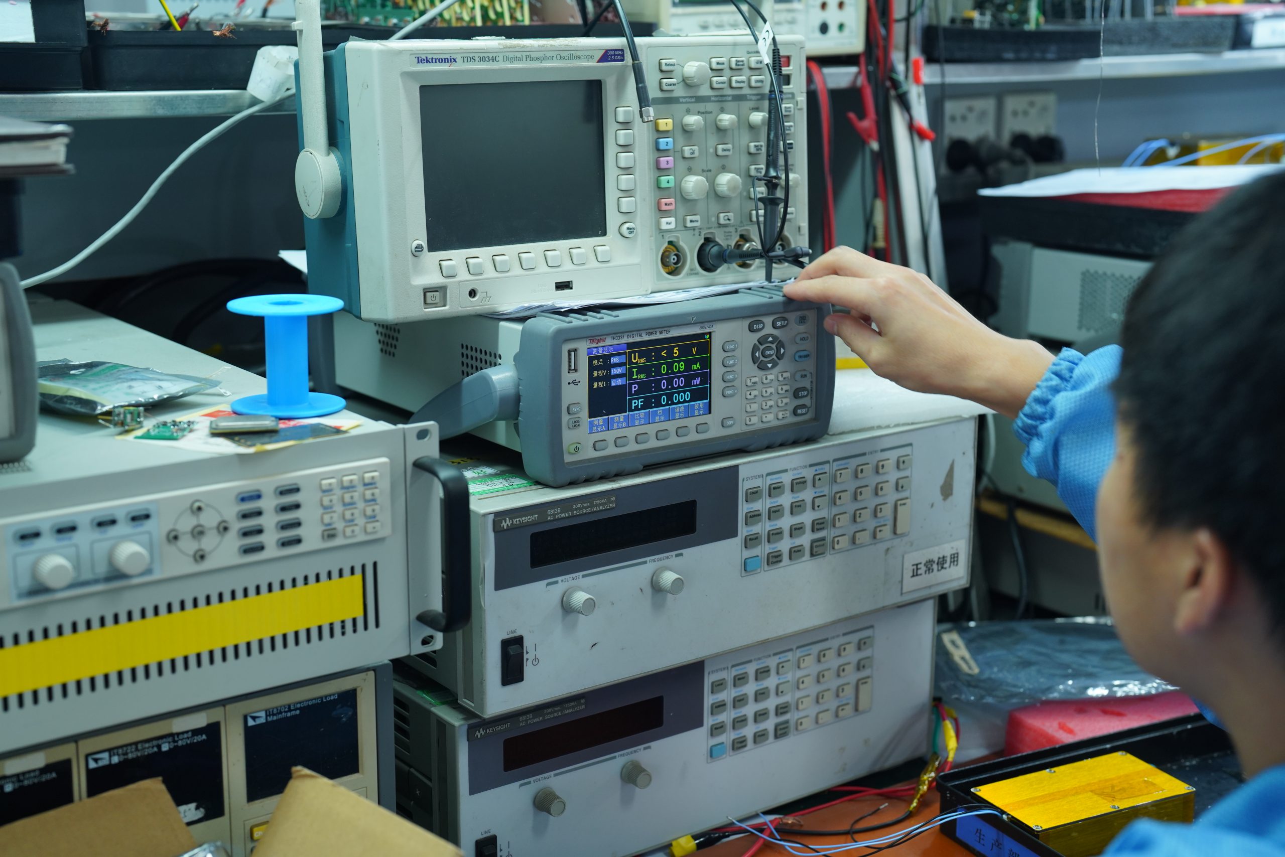
How We Validate This
RF Power Amplifier Series

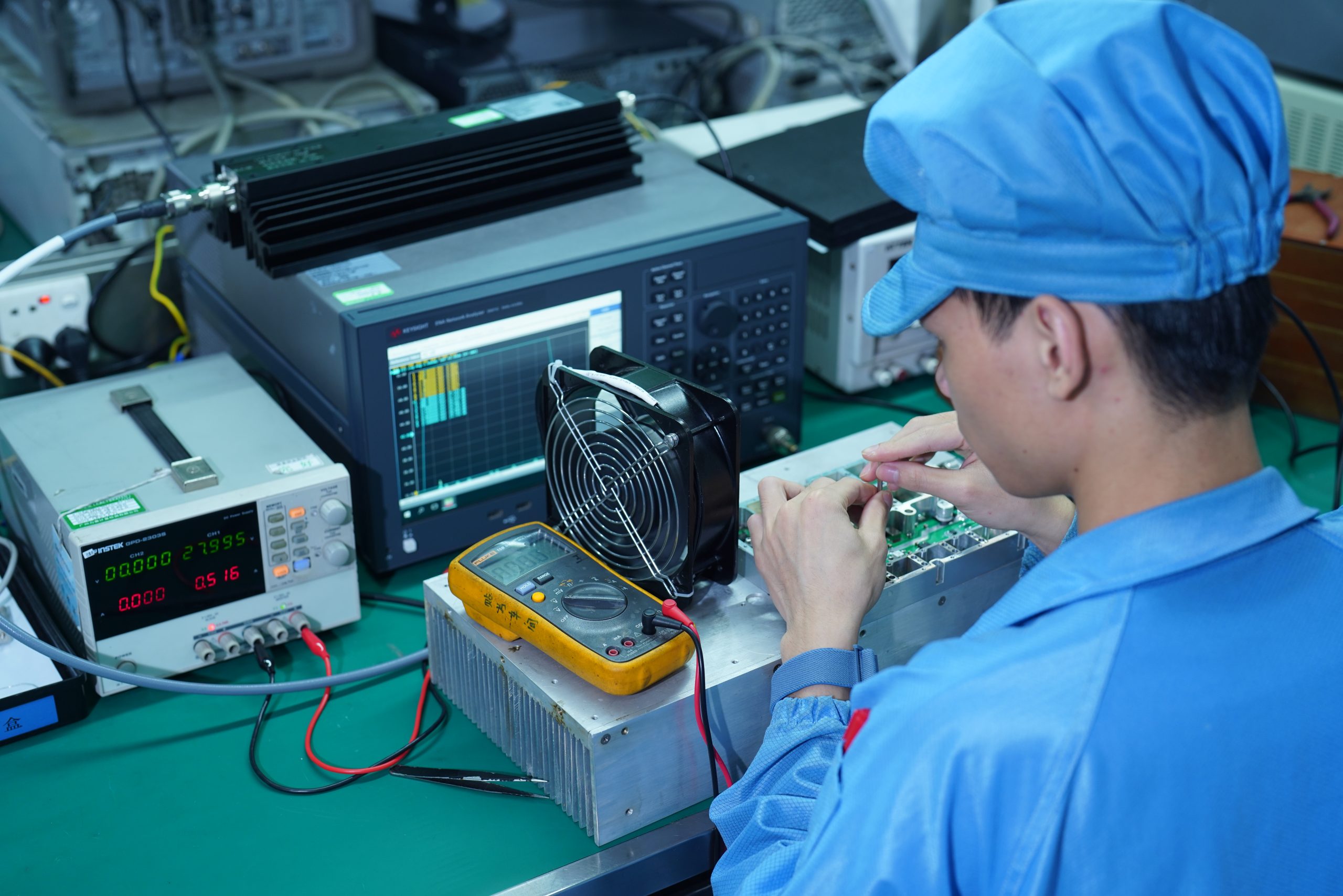
Representative units are tested under defined DC supply and matched-load conditions to verify gain response, output power behavior, and protection performance across the operating band. Sample test data can be shared during engineering review for selected models.

Gain vs. Frequency Validation
S21 measured across 300–2700 MHz at +25 °C ambient and 28 V DC supply. Gain flatness confirmed for representative production units.
Psat and P1dB Verification
Output power compression analysis is performed at defined operating conditions. Results allow system integrators to plan gain budget and required signal headroom accurately.
VSWR Protection Check
Reflected-power protection response is verified under open and short conditions. Circuit response time and drain voltage limiting are confirmed during final unit validation.
Thermal Observation
Baseplate temperature rise is monitored under defined duty cycle and supply voltage conditions to confirm thermal budget compatibility with specified cooling method.
Request Sample Test Report
CorelixRF RF test bench — VNA, calibrated power meter, DC supply, and 50Ω load termination used for amplifier gain and output power validation
VNA Trace ID: CRF-PA27-REF S21 Gain Summary
dB
300 MHz1000 MHz1800 MHz2700 MHz
MEASURED GAIN39.5 dB ±1.2 dB
TEST CONDITION+25 °C / 28 V DC
LOAD CONDITION50 Ω matched
MODELCRF-PA-300M2700M-100W (rep.)
STATUSRepresentative data
Full test report available upon engineering review request
Test Equipment
RF MeasurementVNA + Power Meter
Load Condition50 Ω Calibrated Termination
SupplyRegulated DC (28V)
Custom Engineering

OEM / ODM Customization
Capability

For OEM projects, customization begins with application review, thermal planning, and interface confirmation. This reduces redesign risk during sample and pilot stages. Explore our custom RF power amplifier design service for platform-specific requirements.
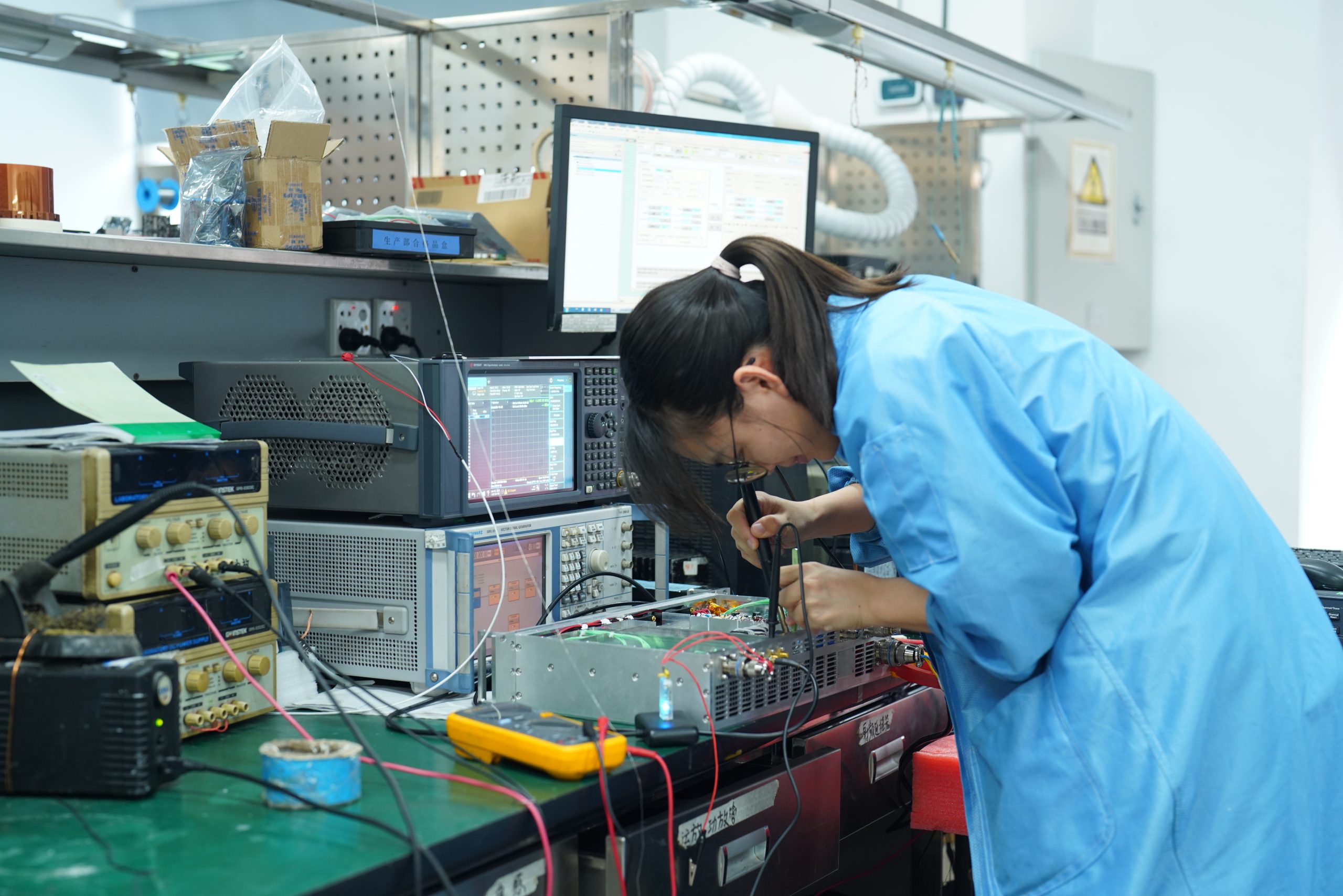
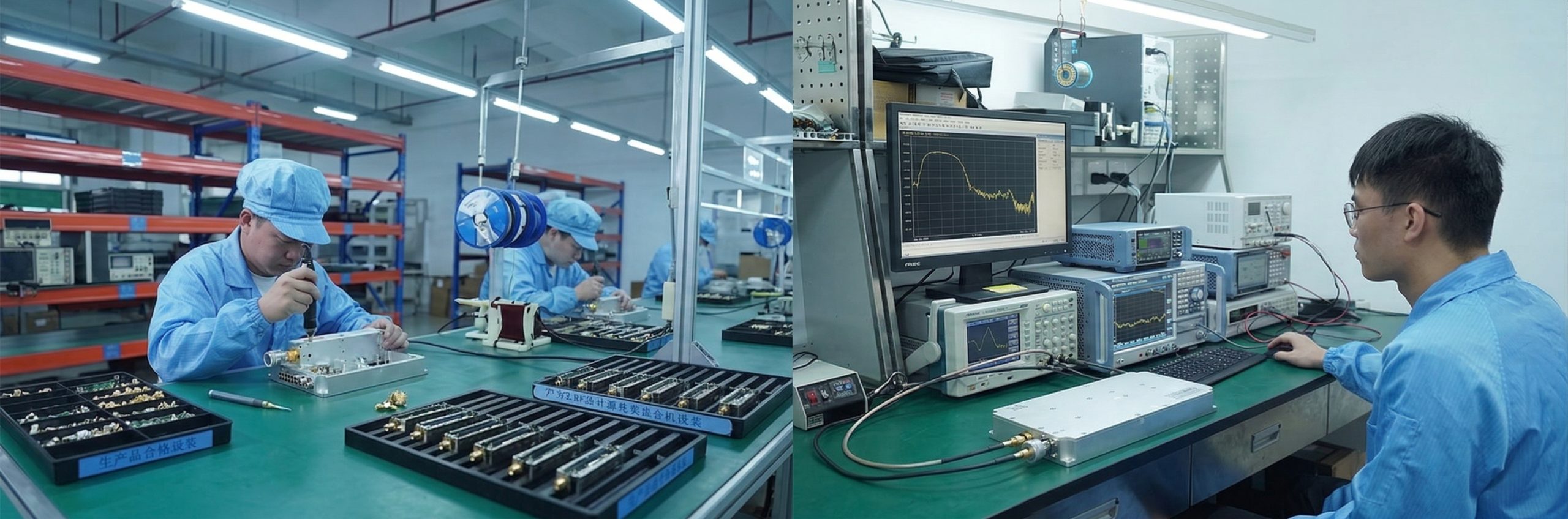
Electrical Customization
Sub-band optimization within the 300–2700 MHz range for higher power-added efficiency (PAE)
Output power tuning to match integration requirements
Gain stage adjustment and driver-stage integration planning
Supply voltage adaptation (28V, 48V, or custom)
P1dB and Psat target specification support
Mechanical Customization
Connector type selection: N / SMA / TNC and custom
Housing and baseplate dimensions matched to platform chassis
Mounting structure adaptation for rack, panel, or vehicle integration
Custom labeling and model coding for OEM product lines
Cooling path design: air, conduction, or liquid-cooled baseplate
CorelixRF OEM customization — different connector types, housing dimensions, and baseplate configurations for RF power amplifier modules
Factory Capabilities: NDA-protected technical project briefing · Direct engineer-to-engineer communication · Batch traceability and factory quality record retention · Transparent lead time and BOM management for OEM/ODM partners
Factory Process

Manufacturing and
Quality Control

Every production unit passes through a defined sequence of verification and assembly steps. This is how we maintain consistency between the first sample and repeat production runs.

Step 01
Incoming Material Verification
Critical RF components and mechanical parts are checked against the project configuration before assembly begins. Component traceability is retained from this stage forward.
Step 02
Assembly & Thermal Integration
Amplifier modules are assembled according to the approved electrical and thermal design. Thermal interface material application and mounting torque are controlled per specification.
Step 03
Final RF Validation
Finished units are checked for gain response, output power, and reflected-power protection before shipment. Test conditions and results are logged per unit.
Step 04
Batch Traceability
Model configuration, test status, and production revision history are retained for each batch. This supports repeat-order consistency and after-sales engineering review.
CorelixRF manufacturing quality control — incoming inspection, module assembly, RF validation, and shipment packaging process overview
Integration Advisory

Integration Considerations
Before Model Selection

Linearity & Headroom

Operating too close to Psat may degrade signal quality in linear links. Verify your P1dB requirements to ensure sufficient waveform headroom for the modulation scheme in use.

Antenna Mismatch

Broadband antenna variation can create high reflected energy across the band. Integrated VSWR protection is recommended to safeguard the amplifier from load-related stress at any operating frequency.

Thermal Stability

Baseplate temperature rise may affect long-term reliability and output power. Always verify thermal margins across expected operating cycles and worst-case ambient conditions before finalizing cooling design.

Engineering FAQ

Common questions from engineers and procurement teams before submitting an inquiry.

P1dB is the point where gain compresses by 1 dB. Specify P1dB for linear communication links (such as QAM or OFDM waveforms) that require low distortion. Psat is the maximum saturated output power. Specify Psat for jamming, electronic warfare, or pulse applications where peak power density is the primary goal.
An integrated sensing circuit continuously monitors reflected power at the output. When a mismatch is detected — caused by an open, short, or poorly matched load — the circuit limits drain voltage within microseconds, preventing damage from high reflected energy.
Yes. As a factory we support sub-band optimization — tuning for higher efficiency within a specific 100–200 MHz window — as well as OEM/ODM adjustments to connectors, housing dimensions, gain stages, and output power levels.
Please share your target band, required output power, operating mode (CW or pulse), supply voltage, duty cycle, cooling condition, and application background. This allows our engineering team to provide a focused technical recommendation rather than a generic model suggestion.
Yes. For projects operating within a narrower sub-band, frequency tuning can improve power-added efficiency, gain response, and thermal balance. Please provide your target sub-band when submitting an engineering review request.
Direct Manufacturer Contact

Request Technical Review
From the Manufacturer

CRF-PA-300M2700M SERIES — TECHNICAL ASSESSMENT REQUEST

Specify your target frequency band, output power, duty cycle, and supply requirements. Our engineering team will respond with a technical feasibility review within 2 business days.

Engineering review within 2 business days · NDA available for OEM/ODM projects · Sample and batch production support · Technical recommendation based on duty cycle and thermal conditions
Why review directly with the manufacturer
Engineering response within 2 business days with model-specific recommendation
NDA available for OEM/ODM project discussion before any technical disclosure
Technical review covers duty cycle, drive level, thermal path, and integration requirements
Sample test data available for selected models during engineering evaluation
Prototype and batch production support from the same engineering team
No commitment required to start a technical discussion